Power to the Pedal
How to Power Domestic Appliances with your Ebike Hub Motor
First draft published 16 January 2020
Forget “clean coal” it’s a myth, North Sea gas is cleaner than coal but it is still a greenhouse gas emitting fossil fuel, nuclear works but has serous safety issues, solar is great if you have a roof and sunshine, tidal might be OK if you can dam up an estuary, wind is the answer when it is windy.
But what are you supposed to do when you’re out on your bike and you;
- fancy watching a film on a large screen LED TV you just happen to have brought with you?
- want to power a local band giving an outdoor performance using bicycles?
The ChiCycle team imagine a green, pedal powered future so we looked into these ideas as fun ways to illustrate how we use electrical energy in every day life.
Feasibility: it is obviously possible on a small scale:
Science Fiction: These ideas feature in the Black Mirror episode Fifteen-Million-Merits
Indeed we have recently (Nov 2024) met up with Electric Pedals in London who have made programs with the BBC showing bikes can power virtually anything.
Disclaimer
What follows is an indication only of what ChiCycle has tried and tested. We give no guarantee these ideas are safe for individuals using the equipment nor safe for the equipment being powered. If you choose to replicate any of the setups that ChiCycle has employed, be certain to consider the mechanical risks and risks of mains voltage electricity if stepping up the output to power mains appliances. If a sensible approach is taken there should be little risk but reasonable precautions are necessary.
What Hub Do I Need?
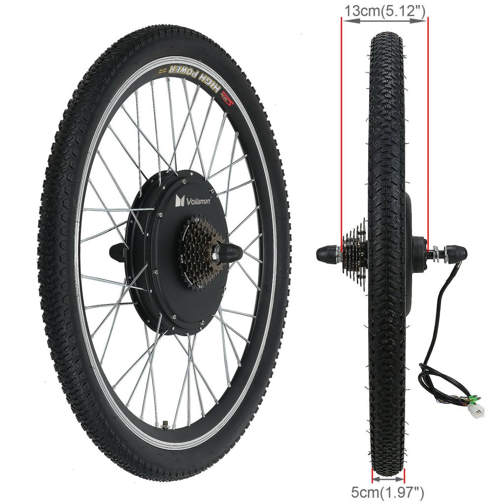
ChiCycle have been experimenting with a rear EBike hub with built in dérailleur gear sprockets. Some EBike hubs won’t easily work as generators as they have freewheels to stop the motor turning unless it is powering the bike. However most other EBike hubs without motor freewheels will make very efficient generators as well as drive motors. You will probably want to find a way to hold the rear wheel off the ground so the E-motor can generate electricity without the bike having to move forward. We have been testing a wheel very similar to the one shown below.
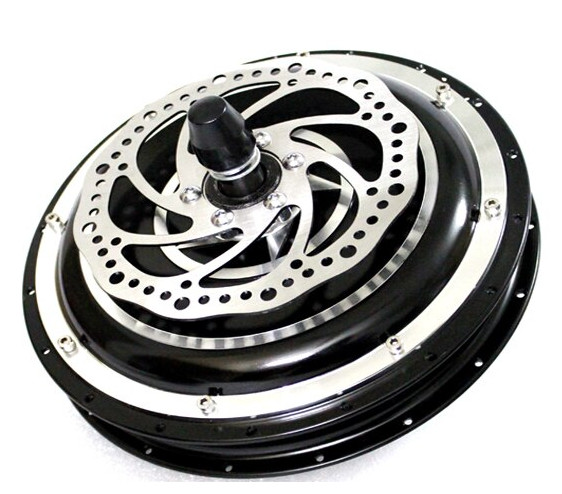
An alternative idea stolen from Barreg Cycles, Fishbourne, is to drill out a single rear sprocket and bolt it onto a front motor hub where the brake disk should normally go. A front hub with brake disk is shown below.
ChiCycle assume the hub is going to work most efficiently as a generator in top gear. However this is just an educated guess.
Most hubs have fine wires for their hall sensors. These are of no significance if the hub is to be used as a crude simple generator.
There are usually three thick wires that connect directly to the three phase motor windings.
At a sustainable but energetic peddling rate in top gear we measure approximately 18 volts AC at 100 Hz with no load, across one phase winding.
Spinning the peddles a little faster gives 24 Volts between each phase. Three 24 volt 21 Watt indicator bulbs can be connected between each phase and fully illuminated by pedalling quite quickly.
Powering TVs, computers and other consumer electronics.
Most TV’s, computers, smart phone chargers and even Christmas tree lights operate using high frequency switch mode transformers. Most UK and European consumer equipment appears to have an extremely wide range of input voltages over which devices power up and operate without issue. Most specifications cover a range of 100V to 240V mains AC in the equipment’s documentation but since these devices internally rectify the incoming AC supply the AC frequency is not critical. In fact most devices seem happy to operate on a DC supply! Ideal rectification of 240 V mains would give 240 V (ac) × √2 = 339 (dc). Assuming the device internal power supply is designed to cope with 20% variation in the mains supply, its storage capacitor and chopper circuit should be able to cope with up to 240 V (ac) × √2 × 1.2 = 407 V (dc). It is likely most UK/EU devices will tolerate higher DC input voltages but finding the upper limit will probably damage the devices internal power supply so this is not an advised activity. Most consumer equipment we have tested, begins working reliably with approximately 100 V dc input. Aiming for a supply voltage under load (at a sustainable pedalling rate) of between 150 and 170 Volts seems a safe option. To achieve this we used a circuit similar to the one shown below.
Most mains powered blenders also work fine from this type of DC supply. Many devices use Universal motors whose field coils are wired in series with the rotor coils. These motors run equally well from AC or DC supplies.
All energy efficient mains light bulbs we have tested so far work OK on this type of DC supply and traditional tungsten and tungsten-halogen work fine too.

Stopping People Pedalling Too Fast
We have discovered that if general members of the public pedal, they can go much too fast while there is little load and produce undesirably high voltages. This is a particular issue with over enthusiastic youths. If powering expensive pieces of equipment such as TVs, excess supply voltages could lead to damage that might be expensive/difficult to repair !
We have solved this issue by creating a voltage activated switch. The switch uses power MOSFET transistors to connect a 1 Ohm 280 Watt resistor across the low voltage (A & B) outputs (referred to in the diagram above). The resistor is switched in when the low voltage output reaches 35 Volts and switches out again when the voltage falls to approximately 25 Volts. From the cyclists perspective this produces a defined resistance opposing pedalling effort but only when the cadence becomes too fast. Even extremely athletic cyclists are unable to to pedal fast and hard enough to overcome this speed limiter (it would require over 1,250 watts of human power to over come the brake). The excess energy mostly goes into warming the 1 Ohm resistor. The switch circuit is designed to turn the MOSFET on and off fast. This prevents the transistors being destroyed through overheating.
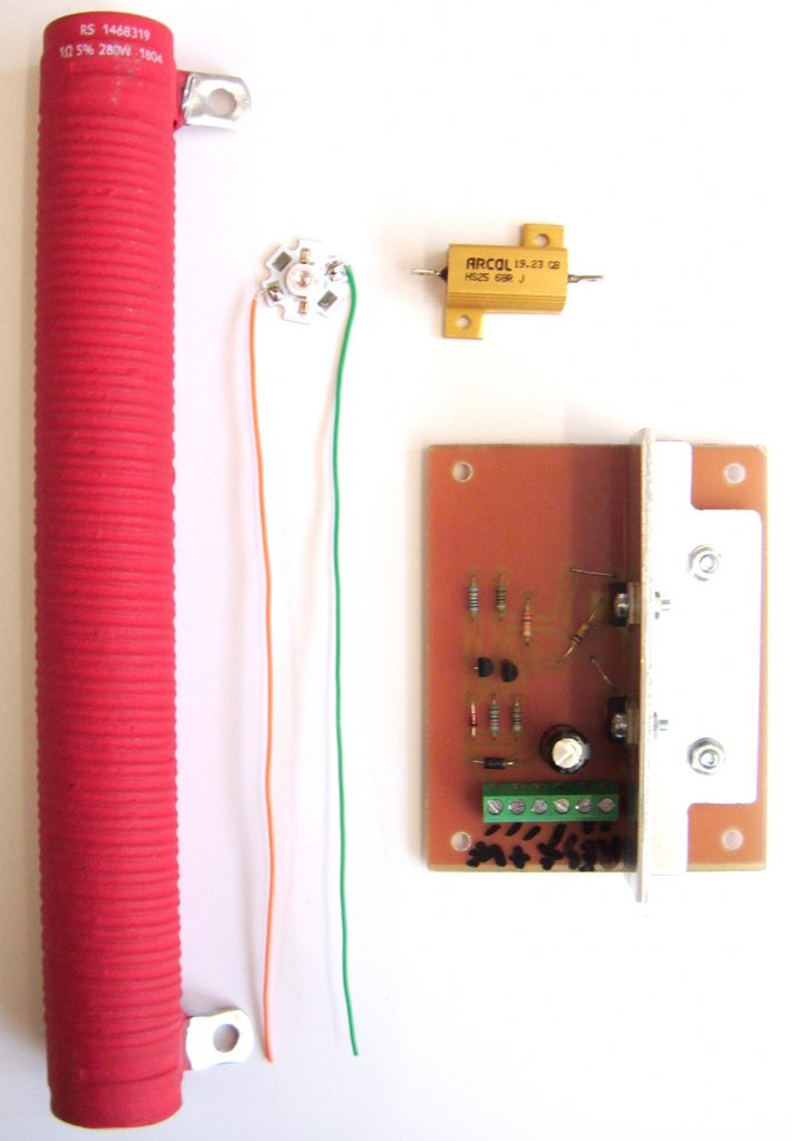
The components of the brake system are shown below. The smaller golden 68 Ohm 25 Watt coloured resistor is connected in series with a 3 Watt red LED. These two components are connected in parallel to the large red 1 Ohm 270 Watt resistor to give a bright red warning light that comes on when the electronic brake activates.
The original electronic brake circuit design (available here) used only one STP55nf06 Power MOSFET transistor but the circuit board design (available here) allows two identical power transistors to be connected in parallel to ensure reliability in handling the heavy switching current. The speed when the brake activates can be adjusted by altering the value of the 27kOhm resistor shown in the circuit diagram. Reducing this resistance slightly will lower the voltage when the brake activates.
Amplifying Sound
These devices are available from E bay. The low voltage rectified output supply (terminals A & B) can power this very adequately.
WONDOM 2 X 100 Watt 6 Ohm Class D Audio Amplifier Board – TDA7498 Module Stereo

Business seller information
Sure Electronics
Zhang Cheng
3F, Building F6, No.9 Weidi Rd., Xianlin
210000 Qixia Dist., Nanjing, China, 江苏省
China
Our unit does deliver 100 Watts RMS per channel into 6 Ohm loads with a 36 Volt power supply input but in normal use the ebike supply voltage will be lower and there will be a reduction in output power. However it still sounds loud even used outdoors! A laptop or phone can supply a signal directly to the amplifiers phono connectors. For use with a microphone a preamplifier is needed and we will publish details of something suitable when we have arrived at a satisfactory design for this.
Our current Bike Powered Equipment risk assessment for events is available on the following link.
ChiCycle-Cycloke-Risk-Assesment-Oct2024-SU-Format
Images, Video and Descriptions of ChiCycle Bike Powered Equipment
A cheap 2nd hand Halfords Frenzy bike has proved a reliable basis for the ChiCycle generator bike. Unfortunately, it is prone to rust and needs frequent cleaning and rust treatment.
A useful feature of this set up, is the stand can be hinged up allowing the bike to be ridden to events. The stand can be quickly lowered so it can quicky begin use to generate electricity.

An electronic speedometer is fitted to the handlebars.
The speedometer is based around an analogue LM3914 Dot/Bar Display Driver IC.
Circuit diagram and component values are available here.
An Inkscape SVG file of the printed circuit is available here. It is a mirror image of the copper traces. the components are shown on a separate drawing layer that can be turned off using Inkscape when printing the board artwork.
We used cheap ebay LED bar displays but discovered the different colour LEDs had wildly differing intensities. We worked around the issue by using different currents to drive the LEDs so they all look roughly the same brightness.
The speedometer is connected directly to the three phase output from the ebike hub rear wheel.

A sturdy wooden case houses electronics used to drive speakers and to provide mains like power for equipment.


The wiring inside the box follows the diagram of the power converter shown earlier in this post.

The WONDOM 2 X 100 Watt 6 Ohm Class D Audio Amplifier Board can be seen below coupled to the audio mixer (that I still have not got around to documenting yet).

Quite a lot of thought went into designing the audio mixer so it can share the same power supply rails as the power amplifier.
There were some challenges to sharing power rails but these have been nicely overcome.
However the op-amps used are a little noisy giving a noticeable hiss when the volume is turned all the way up. I will use lower noise op-amps next time.
Other than that, the quality of sound is clear and crisp.

Transformers, rectifiers and smoothing capacitors (smoothing for low voltage supply only) shown below.

Components of the electronic brake that stop people pedalling too fast. are shown below.

When the electronic brake engages, an ultra-bright red LED lights up on the front panel.
It is labelled overload just to be dramatic and appeal to kids, but it safely and effectively slows riders cadence if people ride too fast.
Prior to each use at an event, this feature is to be tested to be sure it works correctly.

ChiCycle Bike Powered Equipment in Action
Handlebar speedometer in action.
Powering up audio PA and LG smart television.
Powering up Optima projector (could have also powered up audio PA with film sound but did not do that in this instance)
Setup Notes for Events
TOSLINK Fibre Optic to RCA Stereo Audio Adapter Link