West of Chichester Development Junction and Cycle-Path Geometry Concerns
The following planning application contains details of junctions on the development spine road. CC/20/01046/REM – Case Officer: Steve Harris. 50 dwellings with associated parking, landscaping, informal open space and associated works (Phase 5, Parcel F, permission 14/04301/OUT).
A typical junction from this plan is shown in the image clipped from document CB_70_068_P5_F_000 (SITE LOCATION PLAN) is shown below.
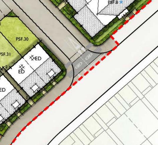
Developers have proposed that the pavement shown to the north east side of the spine road could be designated as a shared use path carrying both pedestrians and two way cycle traffic.
Proposed Junctions do not Pass DfT Recommended Visibility Splay Analysis
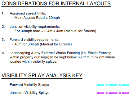
DfT Cycle infrastructure design (LTN 2/08) page 53 gives the following guidance on Visibility Splay Analysis
9.1 Visibility criteria at junctions and crossings
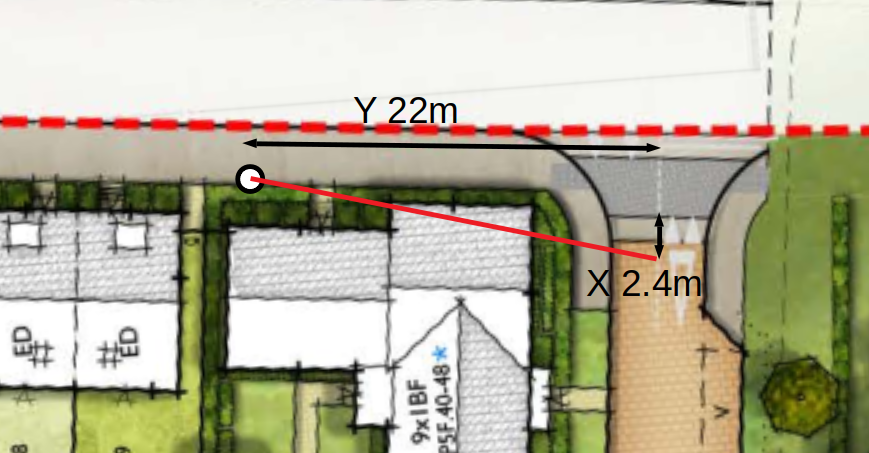
9.1.1 Where a cycle track meets a road, visibility splays are required to ensure cyclists can see and be seen by approaching motorists. Splays are defined by their X and Y distances.~~~~~~~~~~~~~~~~~~~~~~~~~~
9.1.2 MfS normally recommends an X distance (of 2.4 metres) which allows one car driver at a time to check along the main alignment before exiting the minor arm.~~~~~~~~~~~~~~~~~~~~~~~~~
9.1.3 The circumstances are different at a cycle track junction–for one thing, the speeds involved are lower. In this case, longer X distances are preferred, as they can reduce cycling effort and may enhance safety. ~~~~~~~~~~~~~~~~~~~~~~~~~
Y distance is given from the table below from DfT Manual for Streets page 91.
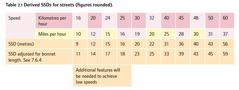
22 metres is appropriate for Y as the DfT recommend a 20 mph Cycle-way Design Speed for routes intended predominantly for utility cycling. Cyclists commuting towards Chichester Station travelling South East, will be running on a significant down hill incline and will easily be able to achieve 20 mph.
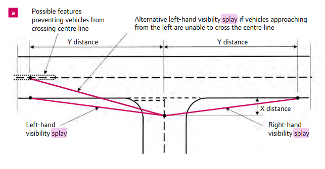
DfT Manual for Streets page 93 gives an examples of Splay Analysis and an appropriate example is shown in the image below.
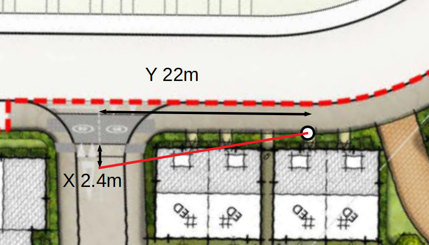
Chichester Cycle Forum visibility splay analysis of the proposed development plans highlight road safety issues. Images of analysis shown below.
Developers have Submitted Splay Analysis that Ignores Visibility of Cyclists
An example of the developers junction splay analysis can be seen by viewing document PRIMARY_ACCESS_ROAD_VISIBILITY_SPLAY_ANALYSIS_SHEET_4_OF_4__A1 that is part of planning application 18/01587/REM
A section of this drawing is shown below.
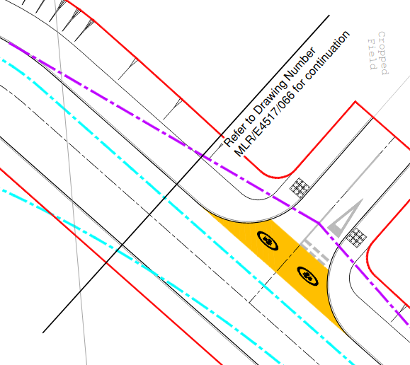
Notice that the splay lines do not include the cycleway that motorists will need to see clearly in order to give way to cyclists who are intended to have priority.
Part of the drawing key is shown below
Although it is usual to analyse viability splays that align with the main axis carriageway kerb, this will clearly not be appropriate in this case because cycle traffic has been diverted onto the pavement and motor vehicles are intended to give way to the cyclists at the side road junctions. It will not be possible for motor vehicles to give priority to cyclists unless it is made possible; for the cyclists to be within the drivers visibility spay.
The DfT Manual For Streets Page 92 explains.
7.7.3 The Y distance represents the distance that a driver who is about to exit from the minor arm can see to his left and right along the main alignment. For simplicity it is measured along the nearside kerb line of the main arm, although vehicles will normally be travelling a distance from the kerb line. The measurement is taken from the point where this line intersects the centreline of the minor arm (unless, as above, there is a splitter island in the minor arm).
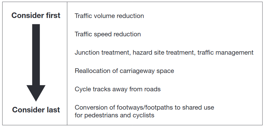
However, DfT Cycle infrastructure design (LTN 2/08) page 10 guidelines recommend against routing cyclists along the pavement.
1.3.2 The road network is the most basic (and important) cycling facility available , and the preferred way of providing for cyclists is to create conditions on the carriage way where cyclists are content to use it, particularly in urban areas. There is seldom the opportunity to provide an off carriage way route within the highway boundary that does not compromise pedestrian facilities or create potential hazards for cyclists, particularly at side roads. Measures that reduce the volume or speed of motor traffic benefit other road users by making the roads safer and more pleasant for them to use. New build situations provide good opportunities for creating attractive high quality infrastructure for cyclists, either in the form of quieter roads or direct cycle routes away from motor traffic.
DfT Cycle infrastructure design (LTN 2/08) page 10 also shows a graphic reiterating that routing cycleways along pavements in urban areas is considered the least favoured of all options.
DfT Cycle infrastructure design (LTN 2/08) page 53 guidance states.
9.1.1 Where a cycle track meets a road, visibility splays are required to ensure cyclists can see and be seen by approaching motorists.
Clearly it is vital for everyone safety that there is adequate visibility provided at side road junctions so that cars do not pull out in front of the cyclists who have right of way.
Visibility Compliance Relies on Miniature Front Garden Architecture
It is also of concern that developers splay analysis states compliance with DfT visibility criteria will rely on peoples front gardens having fencing, shrubs and hedges that must remain under 600mm (24 inches) in height.
Landscaping & any External Works Fencing (i.e. Picket Fencing within property curtilage) to be kept below 600mm in height where located within visibility splays.
A brief survey around the Chichester area should quickly confirm that most residents choose taller planting and landscaping in their front gardens. Very few popular hedges or shrubs will be happy to be pruned down to 600mm (24 inches) in height!
The Cycleway Width will be Constrained at Junctions.
At the mouth of the junctions is a traffic calming feature. Its start and finish has inclines leading to a level “table” section in its middle part. Because the level “table” section is offset from the pathway, cyclists will have to hug the side of the pavement furthest from the kerb when transitioning onto the table to cross the side roads. It is presumed the transition between pavement and the inclined sections of the traffic calming will not be flush. This issue is illustrated in the image below.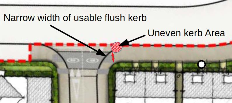 .
.
The cycleway width is shown to be severely restricted at junction by uneven kerb area
Minimum Path Width Should be 3.45 Metres because Path is Bounded by Shrubs, Hedges and a Kerb
The Department for Transport (DfT) publish a national guideline document about creating the infrastructure to encourage cycling, Cycle infrastructure design (LTN 2/08).
On page 42 it gives the following guidance on path widths for off-road cycleways.
8.5 Width requirements
8.5.1 The minimum widths given in this section relate to what is physically required for the convenient passage of a small number of users. They do not take into account the need for increased width to accommodate larger user flows. Wherever it is possible, widths larger than the minimum should be used. Practitioners should not regard minimum widths as design targets.
On page 43 the guidance on path widths continues.
8.5.3 Where there is no segregation between pedestrians and cyclists, a route width of 3 metres should generally be regarded as the minimum acceptable, although in areas with few cyclists or pedestrians a narrower route might suffice. In all cases where a cycle track or foot way is bounded by a vertical feature such as a wall, railings or kerb, an additional allowance should be made, as the very edge of the path cannot be used. Table 8.2 provides the recommended width additions for various vertical features.
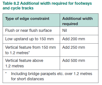
The shrubs and hedges that border the path at the junction are vertical features and should be taken into account as requiring additional path width. The same apples to the up stand kerb. The DfT guidelines suggest a minimum path width of 3.45 meters, whereas the usable width shown on the plans narrows to only two metres wide at side junctions (approximately).
Pedestrians have Insufficient Visibility of Oncoming Cyclists
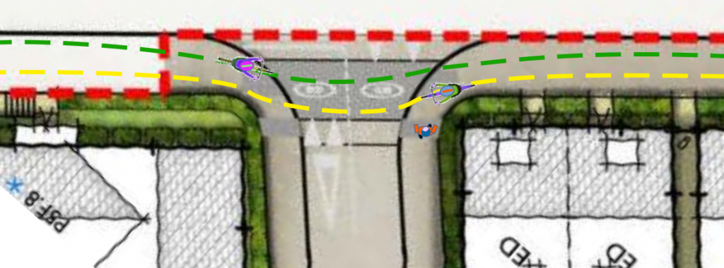
Siting Properties with Shrubs and Hedges Immediately Bordering Cycleway Path Boundary gives Pedestrians Insufficient Visibility of Oncoming Cyclists. This issue is compounded by cyclists having to swerve into the mouth of side junctions to cross the traffic calming table. It is important to remember many footpath users may not be tall enough to sight approaching cycles over the tops of shrubs and hedges. The issue is illustrated in the graphic below.
Visibility of Home Owners Emerging from Houses and Junctions Appears Inadequate for DfT Recommended 20 mph Cycle-way Design Speed
DfT Cycle infrastructure design (LTN 2/08) page 41 gives the following guidance on design speeds for off-road cycle-ways
8.2 Design speed
8.2.1 On commuter routes, cyclists usually want to be able to travel at speeds of between 12mph and 20mph, preferably without having to lose momentum. Frequent road crossings, tight corner radii, the presence of other users and restricted width or forward visibility all affect the speed with which cyclists can travel and the effort required. Cyclists tend not to favour cycle routes that frequently require them to adjust their speed or stop.
8.2.2 A design speed of 20mph is preferred for off-road routes intended predominantly for utility cycling. This provides a margin of safety for most cyclists. The average speed of cyclists on a level surface is around 12mph.
It may be practical for a property entrance to be on a pavement but is it really a realistic proposal to have a property entrance on a cycleway with a design speed of 20mph? As discusses earlier, the cycles will often have to ride away from the kerbside and closes to house entrances to have a continuous flush surface for the wheels to run on. Chichester Cycle Forum members feel this arrangement may make both homeowners and cyclists feel uncomfortable.
Lamp Posts will be set in the middle of the Cycle-Way
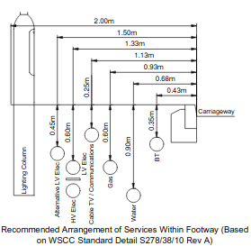
18/01587/REM document MLR/E4517/058 STREET LIGHTING LAYOUT SHEET 4 OF 4 (A1) shows a street light layout and a diagram of how the lampposts will be positioned almost in the centre of the cycleway, less than 2 meters from the curb. The lamp-post positioning positioning diagram from the drawing is shown below.
DfT Cycle infrastructure design (LTN 2/08) page 16 offers the following guidance on Critical distances to fixed objects
2.2 Dynamic envelope
2.2.1 At low speeds, cyclists are prone to wobble and deviate from a straight line. For most cyclists, a speed of 7 mph (11km/h) or more is required to ride comfortably in a straight line without a conscious effort to maintain balance. Above 7mph, the amount of deviation, i.e. the additional width needed when moving, is 0.2 metres. Below this, deviation increases–at 3mph deviation is typically 0.8 metres (seeFigure2.1). Hazards such as uneven gully gratings may cause cyclists to deviate from their chosen line. Additional width for cyclists is recommended where such hazards exist. 2.2.2 For simplicity, the dynamic width (actual width plus deviation) of a cyclist on the road may be taken as 1 metre.
2.3 Critical distances to fixed objects
2.3.1 The following minimum clearances (Table2.1) are recommended and should be increased where possible. They are measured between the wheel and the object
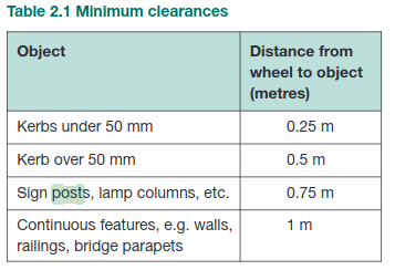
The Chichester Cycle Forum interpret this as a single cycle requires 1 meter “wobble room” and an additional 750 mm clearance on one side to pass a lamp-post, plus an additional 250 mm clearance on the other side from the kerb edge.
This indicates that according to the DfT guidelines, there will not be enough clearance for cyclists to ride along the cycleway even in a single direction or without sharing the space with pedestrians. There will not be enough room either side of the lamp-posts for them to safely ride on the pavement.
An illustration of the proposed lamp-post position in the cycleway is illustrated below.